8.10.3.8 IfcMaterialLayerSetUsage
8.10.3.8.1 Semantic definition
The IfcMaterialLayerSetUsage determines the usage of IfcMaterialLayerSet in terms of its location and orientation relative to the associated element geometry. The location of material layer set shall be compatible with the building element geometry (that is, material layers shall fit inside the element geometry). The rules to ensure the compatibility depend on the type of the building element.
For a cavity brick wall with shape representation SweptSolid, the IfcMaterialLayerSet.TotalThickness shall be equal to the wall thickness. Also the OffsetFromReferenceLine shall match the exact positions between the two shape representations of IfcWall, that is the IfcShapeRepresentation's with RepresentationIdentifier="Axis" and RepresentationIdentifier="Body". Model view definitions or implementer agreements may provide more instructions on matching between building element geometry and material layer set usage.The IfcMaterialLayerSetUsage is always assigned to an individual occurrence object (and only to relevant subtypes of IfcElement). The IfcMaterialLayerSet, referenced by ForLayerSet, can however be shared among several occurrence objects. If the element type is available (in other words, an instance of the relevant subtype of IfcElementType exists), then the IfcMaterialLayerSet can be assigned to the element type. The assignment between a subtype of IfcElement and the IfcMaterialLayerSetUsage is handled by IfcRelAssociatesMaterial.
Attribute use definition
The IfcMaterialLayerSetUsage is primarily intended to be associated with planar building elements having a constant thickness. With further agreements on the interpretation of LayerSetDirection, the usage can be extended also to other cases, for example to curved building elements, provided that the material layer thicknesses are constant.
Generally, an element may be layered in any of its primary directions, denoted by its x, y or z axis. The geometry use definitions at each specific type of building element will determine the applicable LayerSetDirection.
The following examples illustrate how the IfcMaterialLayerSetUsage attributes (LayerSetDirection, DirectionSense, OffsetFromReferenceLine) can be used in different cases. Normative material use definitions are documented at each element (how these shall be used).
Figure 8.10.3.8.A shows an example of the use of IfcMaterialLayerSetUsage aligned to the axis of a wall.
For a layered wall with extruded geometric representation (vertical extrusion), the layer set direction will be perpendicular to extrusion direction, and can be derived from the direction of the wall axis. With the_DirectionSense_ (positive in this example) the individual IfcMaterialLayers are assigned consecutively right-to-left or left-to-right. For a curved wall, "direction denoting the wall thickness" can be derived from the direction of the wall axis, and it will remain perpendicular to the wall path. The DirectionSense applies as well. According to the IfcWall material use definition the LayerSetDirection for IfcWall is always AXIS2 (that is, along the y-axis), as shown in this example.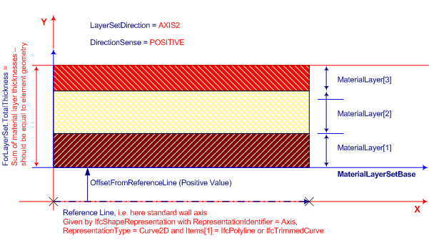
Figure 8.10.3.8.B shows an example of the use of IfcMaterialLayerSetUsage aligned to a slab.
For a slab with perpendicular extruded geometric representation, the LayerSetDirection will coincide with the extrusion direction (in positive or negative sense). In this example, the material layer set base is the extruded profile and consistent with the IfcExtrudedAreaSolid.Position, with the DirectionSense being positive, the individual IfcMaterialLayers are built up from the base towards the positive z direction in this case. According to the IfcSlab material use definition the LayerSetDirection for IfcSlab is always AXIS3 (that is, along the z-axis).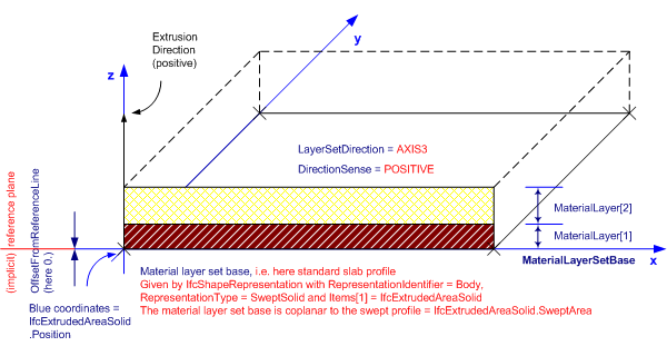
Figure 8.10.3.8.C shows an example of the use of IfcMaterialLayerSetUsage aligned to a roof slab with non-perpendicular extrusion.
For a slab with non-perpendicular extruded geometric representation, the guidelines above apply as well. The material layer thickness and the OffsetFromReferenceLine are always measured perpendicularly, even if the extrusion direction is not perpendicular. Therefore the total material layer thickness is not equal to the extrusion depth of the geometry.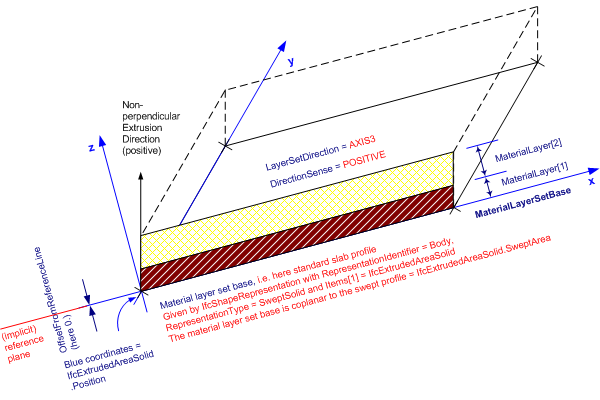
8.10.3.8.2 Entity inheritance
8.10.3.8.3 Attributes
| # | Attribute | Type | Description |
|---|---|---|---|
| IfcMaterialUsageDefinition (1) | |||
| AssociatedTo | SET [1:?] OF IfcRelAssociatesMaterial FOR RelatingMaterial |
Use of the IfcMaterialUsageDefinition subtypes within the material association of an element occurrence. The association is established by the IfcRelAssociatesMaterial relationship. |
|
| Click to show 1 hidden inherited attributes Click to hide 1 inherited attributes | |||
| IfcMaterialLayerSetUsage (5) | |||
| 1 | ForLayerSet | IfcMaterialLayerSet |
The IfcMaterialLayerSet set to which the usage is applied. |
| 2 | LayerSetDirection | IfcLayerSetDirectionEnum |
Orientation of the material layer set relative to element reference geometry. The meaning of the value of this attribute shall be specified in the geometry use section for each element. For extruded shape representation, direction can be given along the extrusion path (e.g. for slabs) or perpendicular to it (e.g. for walls). The LayerSetDirection for IfcWall shall be AXIS2 (i.e. the y-axis) and for IfcSlab and IfcPlate it shall be AXIS3 (i.e. the z-axis). Whether the material layers of the set being used shall 'grow' into the positive or negative direction of the given axis, shall be defined by DirectionSense attribute. |
| 3 | DirectionSense | IfcDirectionSenseEnum |
Denotes whether the material layer set is oriented in positive or negative sense along the specified axis (defined by LayerSetDirection). "Positive" means that the consecutive layers (the IfcMaterialLayer instances in the list of IfcMaterialLayerSet.MaterialLayers) are placed face-by-face in the direction of the positive axis as established by LayerSetDirection: for AXIS2 it would be in +y, for AXIS3 it would be +z. "Negative" means that the layers are placed face-by-face in the direction of the negative LayerSetDirection. In both cases, starting at the material layer set base line. the material layer set base line (MlsBase) is located by OffsetFromReferenceLine, and may be on the positive or negative side of the element reference line (or plane); positive or negative for MlsBase placement does not depend on the DirectionSense attribute, but on the relevant element axis. |
| 4 | OffsetFromReferenceLine | IfcLengthMeasure |
Offset of the material layer set base line (MlsBase) from reference geometry (line or plane) of element. The offset can be positive or negative, unless restricted for a particular building element type in its use definition or by implementer agreement. A positive value means, that the MlsBase is placed on the positive side of the reference line or plane, on the axis established by LayerSetDirection (in case of AXIS2 into the direction of +y, or in case of AXIS2 into the direction of +z). A negative value means that the MlsBase is placed on the negative side, as established by LayerSetDirection (in case of AXIS2 into the direction of -y). the positive or negative sign in the offset only affects the MlsBase placement, it does not have any effect on the application of DirectionSense for orientation of the material layers; also DirectionSense does not change the MlsBase placement. |
| 5 | ReferenceExtent | OPTIONAL IfcPositiveLengthMeasure |
Extent of the extrusion of the elements body shape representation to which the IfcMaterialLayerSetUsage applies. It is used as the reference value for the upper OffsetValues[2] provided by the IfcMaterialLayerWithOffsets subtype for included material layers. New attribute added to the end of attribute list. The attribute ReferenceExtent shall be asserted, if an IfcMaterialLayerWithOffsets is included in the ForLayerSet.MaterialLayers list of material layers. The ReferenceExtent for IfcWall is the reference height starting at z=0 being the XY plane of the object coordinate system. |
8.10.3.8.4 Examples

8.10.3.8.5 Formal representation
ENTITY IfcMaterialLayerSetUsage
 SUBTYPE OF (IfcMaterialUsageDefinition);
	ForLayerSet : IfcMaterialLayerSet;
	LayerSetDirection : IfcLayerSetDirectionEnum;
	DirectionSense : IfcDirectionSenseEnum;
	OffsetFromReferenceLine : IfcLengthMeasure;
	ReferenceExtent : OPTIONAL IfcPositiveLengthMeasure;
END_ENTITY;